Configurator Guide
The configurator is a live part builder. Type a dimension and the drawing redraws, and a full engineering drawing builds itself as you go. No CAD software needed. When the part is right, request a quote — a person reviews every printed part, typically within 1 business day. Prefer an interactive walkthrough? Open Help → Take the Tour inside the configurator.
The workspace
Everything about your part stays visible at once. Nothing hides behind a click.
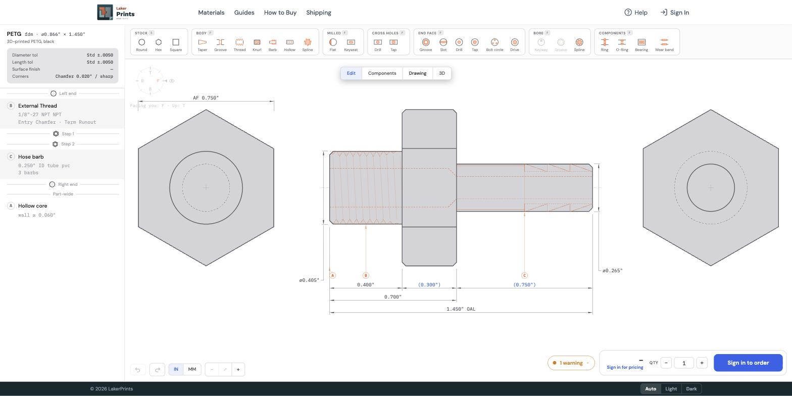
- 1Spec ledger, every face, feature, and dimension, always listed. Values in blue are overrides. Click a row to edit it.
- 2Feature ribbon, add stock, body, milled, cross-hole, and end-face features. Or press F.
- 3Live drawing, redraws in real time as you build.
- 4Edit · Drawing · 3D, switch the whole document between the three views.
- 5Quote & order, quantity and the quote request live here. Sign in to submit; your quote arrives as a link you order from.
Building a part
When you open the configurator you'll start one of three ways: the New Part Wizard (a short guided start, the default on a fresh visit), from a template (pick a starting point from the landing page), or from scratch with a plain shaft. From there you add stock segments and features, then dial in dimensions, tolerances, and finishes.
The feature ribbon
The ribbon groups everything you can place on the part. Click a group to add a feature, or press F anywhere for the same palette. It mirrors the ribbon and lets you type to filter the whole catalog. Each feature opens a define panel where you set its options; place it on the part, and it lands in the ledger with a balloon letter.

- Stock, the bar itself: Round, Hex, or Square segments (see Segments).
- Body, Taper, OD groove, External thread (NPT and straight pipe forms, UN and metric V-threads), Hose barb (sized to your tubing ID), Hollow core (a printed internal flow path), and Knurl.
- Milled, Flat (single, double wrench flats, square, or hex) and Keyseat (single / double / quad, sized to ANSI B17.1 or DIN 6885).
- Cross holes, Drill and Tap across the part: through, to the bore, or blind, with optional counterbore / countersink, and clocking around the part.
- End face, Face groove, Face slot (or saw-cut/split), and axial Drill / Tap into the end: through, to a step, or blind. An axial hole is also how you bore the part.
- Bore (internal), once the part has an axial bore, add an internal KeywayQuoted or Bore grooveQuoted.
Everything is quoted. Printed parts are individually reviewed before pricing — thread fit, wall thickness, and sealing surfaces get human eyes before a number does. Typical turnaround is 1 business day.
Segments & stepped shafts
Segments are the body of the part. Press S (or use the Stock group) to add one in three shapes:
- Round (Q) · Hex (W) · Square (E).
- Hex and Square are sized across the flats (shown as AF); the configurator buys bar stock sized to clear the across-corners dimension.
Build a stepped shaft by adding segments along the part and giving them different diameters. Every diameter change automatically forms a shoulder, so there's no separate "step" tool. Add a Taper (a Body feature) to blend between diameters: set a target diameter, match the neighboring diameter, or specify an included angle or a taper-per-foot, over the whole segment or just an end length.
Parts print within roughly a 9 × 8 × 10″ envelope; most fittings are a small fraction of that. No minimum order — single pieces are welcome.
Editing dimensions
Click any dimension directly on the drawing to change it. Overall length, diameters, feature positions, and feature sizes are all editable in place. The part updates as soon as you commit the value.
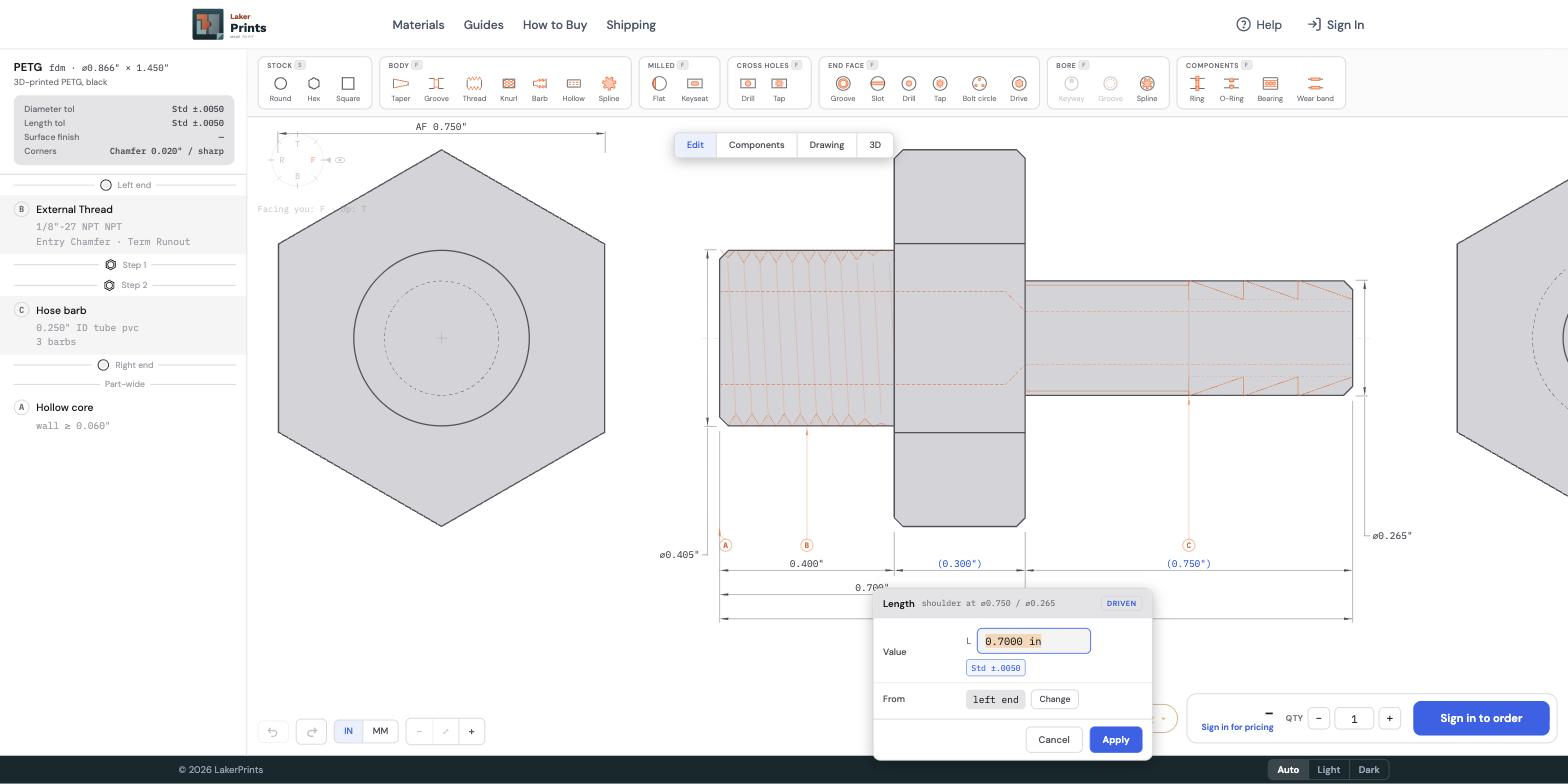
- Type values your way. Enter a number, a fraction (3/8), a mixed number (1 1/2), or an expression (2.5/2, .06+.01), in inches or millimeters (25.4mm, 1/2in). A bare number is in the part's units.
- Driven vs. derived. Some dimensions you set directly; others the builder derives from the rest of the part. Click a derived one, like overall length, and type a value to "drive" it; the editor asks which related dimension to release so the part stays solvable.
- Diameters open with a fit and a tolerance control plus a surface-finish picker (see below).
- Feature positions let you choose which point on the feature is measured (left / center / right / end) and which face or feature it's measured from.
Tolerances, fits & finishes
Tolerances
Every dimension carries a tolerance. Pick a preset tier, or enter a custom band. Set a part-wide default in Part settings; override any single dimension from its editor (overrides show in blue).
| Tier | Diameter & length | Angular |
|---|---|---|
| Loose | ±0.031″ | ±1.0° |
| Standard default | ±0.005″ | ±0.5° |
Need a dimension held tighter? Set a custom symmetric (±) or bilateral (+/−) band on it — tight callouts are part of what the quote review confirms. You can also choose whether the drawing shows tolerances as deviations (1.500 ±.005) or as limits (1.505 / 1.495). Working in millimeters? The metric tolerance bands shown are convenient equivalents. The part is held to the underlying inch specification.
Fits
For a diameter that mates with something, pick a fit by what it does rather than memorizing a class. Choosing a fit sets the tolerance band and a recommended surface finish automatically, both adjusted to the diameter:
| Use it for | Example classes |
|---|---|
| Bearing seat, mounting a rolling-element bearing | g6 · h6 · k6 · p6 |
| Seal journal, a lip-seal running surface | h8 · h11 |
| Bushing journal, a plain-bearing running fit | g6 · f7 · e8 |
| Coupling hub, a press / interference hub mount | p6 · r6 · s6 |
| Locating, precise location, little or no interference | h6 · js6 · h7 |
Bores (internal diameters) get the hole-basis equivalents (H7, P7, and so on). Thread fit classes follow the thread form (2A/3A for UN inch threads, 6g/6H for metric, 2G/3G for ACME) and key fits use ANSI B17.1 classes (CL1/CL2/CL3). You can always override a fit's tolerance or finish, or clear the fit entirely.
Surface finish
Printed parts ship As Printed — layer lines are part of the deal, and the drawing's finish note says so. Sealing surfaces (gasket seats, barb ramps) are printed with profiles designed to seal as printed; if a surface on your part needs special attention, note it in your quote request.
Part settings
The settings card at the top of the ledger covers the whole part, Material, Stock, and Defaults. Nothing is applied until you hit Apply.
Material
Every part prints in PETG — pick the color: black, green, red, orange, blue, clear, purple, white, or yellow. The color is part of the spec and prints exactly as ordered. See Materials for where PETG shines and where it's honestly the wrong answer.
Defaults
- Units, inch or millimeter (you can also toggle the display units any time from the toolbar).
- Dimension display, deviations (
1.500 ±.005) or limits (1.505 / 1.495). - Surface finish and the three tolerance tiers (diameter, length, angular), the part-wide starting points described above.
- Corner treatments.
- Outside corners: Sharp, Break, Chamfer (.010 / .030 / .060 at 45° or 30°, or custom), or Radius (.015 / .032 / .062 R, or custom).
- Inside corners: Sharp, Undercut (set width & depth), or Radius (.0075 / .015 / .032 / .062 R, or custom).
Edit · Drawing · 3D
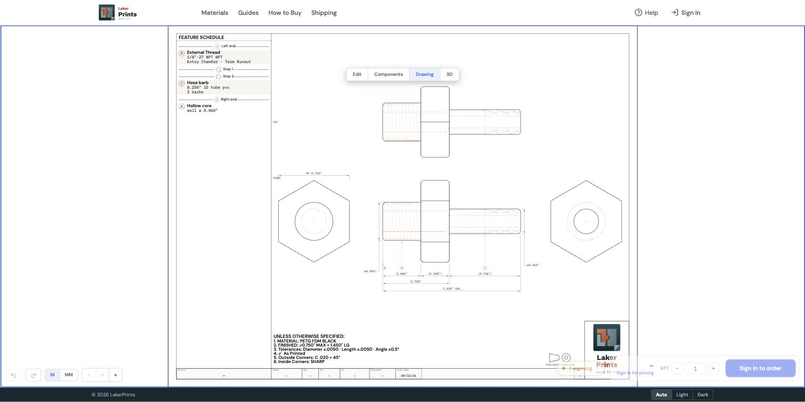
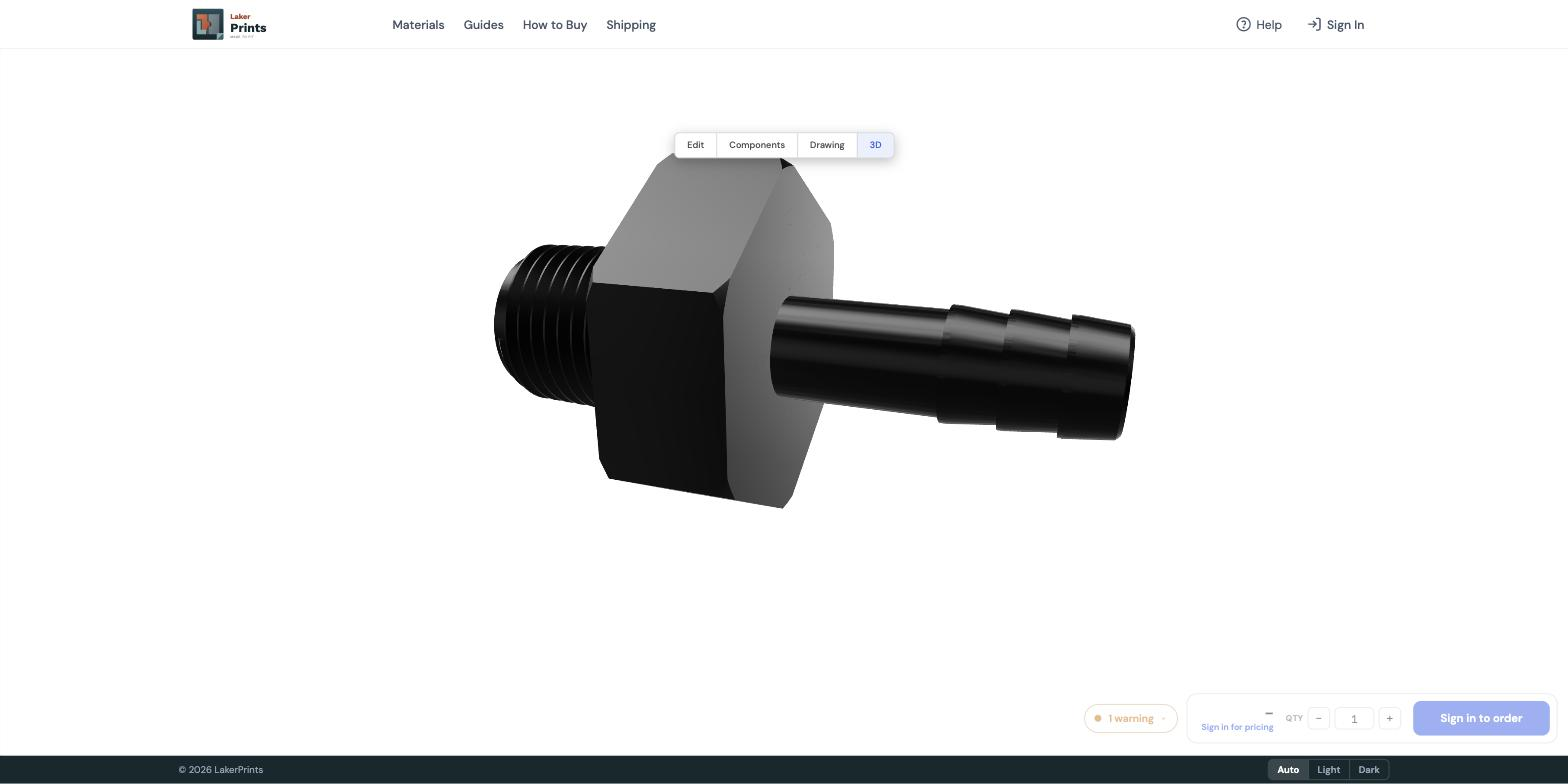
The mode pill switches the whole document between three views. Press D to flip between Edit and Drawing.
Keyboard shortcuts
The same list is available inside the configurator any time you press ?.
| Key | Action |
|---|---|
| F | Add a feature, grouped menu; type to filter the catalog |
| Q W E R · A S · D F · Z X C V | Add from the open F menu (keys mirror the ribbon groups) |
| S | Add a segment (Q W E = Round · Hex · Square) |
| D | Toggle Drawing ↔ Edit mode |
| Enter | Confirm the highlighted item |
| Esc | One step back: clear filter · close menu · cancel placement |
| 1–9 · 0 | Zoom to a segment · fit the whole part |
| Ctrl/⌘ Z · Ctrl/⌘ ⇧ Z | Undo · redo |
| ? | Open the shortcut sheet |
Quotes & ordering
Build the part, set the quantity, and request your quote. The person who will print it reviews the configuration — typically within 1 business day — and your quote arrives as a link with the price and a committed lead time.

- Order from the quote link — accept, then check out by card, bank transfer (ACH), or invoice if your account is approved for payment terms. No minimum order; single pieces are welcome.
- Share the quote — the link carries full part details and pricing, so anyone who needs to approve the buy can see exactly what's being ordered.
After you order
- Every configuration gets its own part number, a full engineering drawing PDF — the same drawing the shop builds from — and a downloadable 3D STEP model (.stp) on your quote or order page.
- Orders can't be modified once placed. If you need a change, configure a new part or open a previous order as a starting point.
- Your order and quote history stays in your account, so reordering or branching an existing part is one click.
Getting more help
- Take the Tour, Help menu inside the configurator (or "Replay tour" from the ? sheet) for an interactive, on-screen walkthrough.
- Tolerances & Specs, see /specs for tolerance tiers, finishes, and material details.
- How It Works, see /how-it-works for ordering, lead times, and common questions.
- Still stuck? Email orders@lakerprints.com and a real person will help.